BACK
NEXT
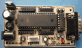
2.7.1. Get to run your stepper
motor
A basic example of stepper
motor driver is shown in figure 2.7.1.1 Notice the separate voltages
for logic and for the stepper motor. Usually the motor will require
a different voltage than the logic portion of the system. Typically
logic voltage is +5 Vdc and the stepper motor voltage can range from
+5 Vdc up to about +48 Vdc. The driver is also an "open collector"
driver, wherein it takes its outputs to GND to activate the motor's
windings.
Figure 2.7.1.1 Driving motor stepper
Step 1st
Build the circuit as shown in figure 2.7.1.1. As you seen on figure 2.7.1.1.
P0.4 trough P0.7 is connected to driver motor stepper. Remember, that
all we want to do with this lesson is write data to stepper motor.
Step 2nd
In this step, you must tipe the assembly program to make your stepper
motor run, we assume that you have already known the editor, we used
MIDE-51 to edit the program. ( Download File
: exp271.zip , Download
Complete Circuit File : StepperMotor.PDF
))
       org 0h
start: mov P0,#11101111b; Turn on driver 1
       call delay       ; call delay time
       mov P0,#11011111b; Turn on driver 2
       call delay       ; call delay time
       mov P0,#10111111b; Turn on driver 3
       call delay       ; call delay time
       mov P0,#01111111b; Turn on driver 4
       call delay       ; call delay time
       sjmp start
;
delay: mov R0,#0
delay1:mov R2,#0fh
       djnz R2,$
       djnz R0,delay1
       ret
end
Step 3rd
Safe your assembly program above, and name it with stepper1.asm (for
example) Compile the program that you have been save by using MIDE-51,
see the software instruction.
Step 4th
Download your hex file ( stepper1.hex ) into the microcontroller
by using Microcontroller ATMEL ISP software, see the instruction.After
download this hex file you'll see the action of Stepper Motor ( of course
if your cable connection and your program are corrected ).
Comments,
questions and discussion about this topic
BACK
NEXT
|