| 
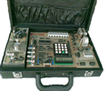
Microcontroller Kits
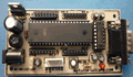
Programmer
and Target 89s51
Simple
Mikrokontroller 89s51 Trainer

Standart
Mikrokontroller 89s51 Trainer

Super Mikrokontroller
Trainer 89s51
+
All Item Include
Programmer
Via USB

|
|
BACK
NEXT
4.1. Basic Turn LED On-Off Serially- RS232 Serial
This experimen is a basic thing you shoul to know, how to convert
data serial to parallel, in this case you may need Basic
serial RS232 Communication to learn.

Figure 4.1. Turn On and Off LED
Step 1st
Build the circuit as shown in figure 4.1. As you seen on figure 4.1.
Remember, that all we want to do with this lesson is send data out trough
PC serially, to turn off and on LED.
Step 2nd
In this step, you must tipe the assembly program to make your serial
working, we assume that you have already known the editor, we used MIDE-51
to edit the program. ( Download File asm and hex : testingLED.zip
)
        org 0h
        nop
        call initserial
gets:   call inchar
        mov P2,a
        sjmp gets
;
initserial:
        mov scon,#52h
        mov tmod,#20h
        mov th1,#-13
        setb tr1
        ret
;
inchar:
        detect: jnb ri,detect;
        clr ri
        mov a,sbuf
        ret
;
End
To get the data from microcontroller serially, computer
must run the program to get data from port communication RS232, in this
experiment I have been used Delphi programming: ( Download
File Delphi : testingLED.zip )
(a)

(b)
Figure 4.2. Delphi Programming to Turn off and On
var
Form1: TForm1;
data,status:byte;
const
base = $3f8;{base address port serial}
lcr = 3; {line control register}
dll = 0; {divisor lacht low byte}
dlh = 1; {divisor lacht high byte}
lsr = 5; {line status register}
Procedure Initserial;
begin
asm
mov dx,base+lcr; {address line control register}
mov al,$80 ; {10000000b = access bit divisor lacht}
out dx,al
;
mov dx,base+dll; {address divisor lacht low byte}
mov al,$30 ; {DLLB = 30h}
out dx,al
;
mov dx,base+dlh; {address divisor lacht high byte}
mov al,$00 ; {DLLH = 00h}
out dx,al
; {In this case Port Serial have}
; { baud rate = 2400 bps}
mov dx,base+lcr;{address line control register}
mov al,$03 ; {00000011b =}
out dx,al ; {bit 7=0, access to Rx buffer & Tx
; {bit 6=0, set break disable
; {bit 5-4-3=000, no parity
; {bit 2=0, one stop bit
; {bit 1-0=11,data lenght 8 bit}
end;
end;
Procedure Send_Data_Serial;
begin
asm
mov dx,base
mov al,data
out dx,al
end
end;
procedure TForm1.FormCreate(Sender: TObject);
begin
Initserial;
end;
procedure TForm1.Button1Click(Sender: TObject);
begin
repeat
asm
mov dx,base+lsr ; {address line status register }
in al,dx
and al,$20 ; {00100000b =not masking bit 5}
mov status,al ; {bit5=Empty Transmitting holding reg}
end;
until status = $20;{If ETHR = 1 then data ready tobe send }
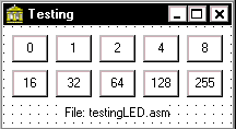
data:=0;
Send_Data_Serial;
end;
procedure TForm1.Button2Click(Sender: TObject);
begin
repeat
asm
mov dx,base+lsr; {address line status register }
in al,dx
and al,$20 ; {00100000b =not masking bit 5}
mov status,al ; {bit5=Empty Transmitting holding reg}
end;
until status = $20; { If ETHR = 1 then data ready tobe send}
data:=1;
Send_Data_Serial;
end;
;{do the same instruction for 2, 4, 6, 8, 16, 32, 64, 128 }
;
;
procedure TForm1.Button10Click(Sender: TObject);
begin
repeat
asm
mov dx,base+lsr ; {address line status register }
in al,dx
and al,$20 ; {00100000b =not masking bit 5}
mov status,al ; {bit5=Empty Transmitting holding reg}
end;
until status = $20; { If ETHR = 1 then data ready tobe send }
data:=255;
Send_Data_Serial;
end;
Step 3rd
Safe your assembly program above, Compile the program that you have
been save by using MIDE-51, see the software instruction.
Step 4th
Download your hex file (testingLED.hex ) into the microcontroller
by using Microcontroller ATMEL ISP software, see the instruction.After
download this hex file you'll see the action of serial transmition(
of course if your cable connection and your program are corrected ).
Comments,
questions and discussion about this topic
BACK
NEXT
|
|
|
|
